Finishing the forward fuselage

First off, I finally lined up a job, so the rapid pace of progress is going to slow back down shortly.  I’m going to work for a Silicon Valley autonomous car company, so we’ll be packing up and leaving Houston for sunny California.  I’m looking to live south of the Bay which will be more convenient to an airport (only 10 minutes!).  The new gig is across the street from Palo Alto airport so I can even fly to work if I choose.  I’ll have to load up the shop and truck it to California, but I’ve done this before.  I really hope this is the last time I have to move the plane by land.

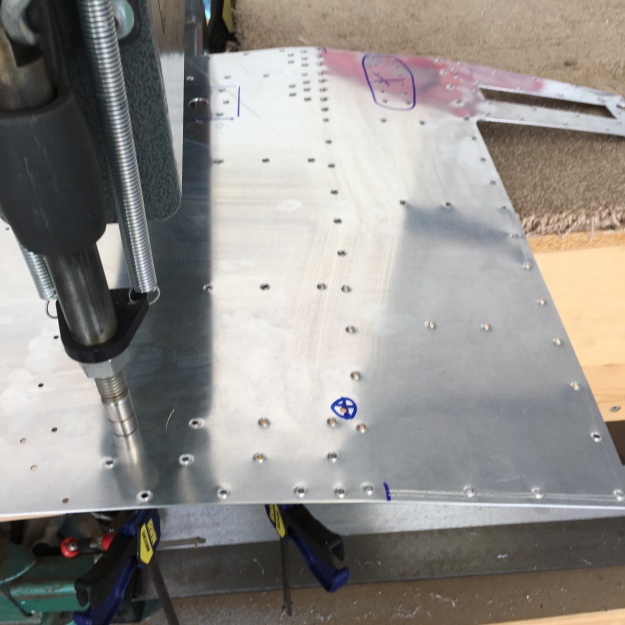
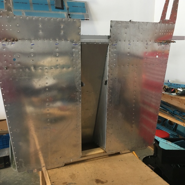
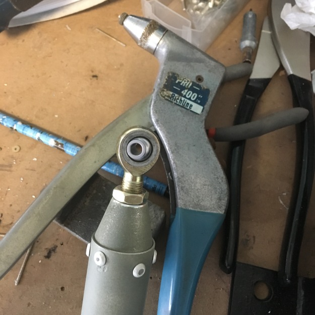
But before I go, I want to get the big join done so that I can move the fuselage in one piece rather than a collection of smaller things (plus my hangar neighbor has offered to help me paint the cockpit interior if I get it done over Christmas!).  With the front side skins prepped and the attachments ready to go it was time to start riveting them on (Section 29-12).  I did some of the work flat on the ground, but most of it was done with the skins clamped to saw horses.  That made it easy to reach the various rivets.  I was able to back rivet most of them using my back rivet bucking bar.


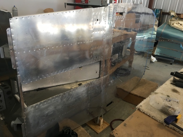
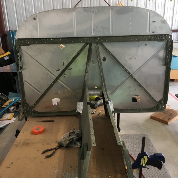
With that done, I was able to cleco the skins to the front half fuselage and make it look almost like a real airplane cockpit!

2018-11-26 13.18.33

There are a bunch more parts to attach that have to go in after the skins are roughly in place.  So another day of part prep and priming is required to get there.   The center channel cover section has to be bent a small amount.  I did it by clamping pieces of wood across the channel and my bench and then carefully bending across the table edge.  I got a nice, straight bend with a gentle curve.  It fit well.

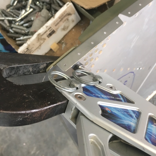
Then everything is clecoed to the skins and you get to riveting.  It took a few days to get everything done.  I was able to do the side attachments solo (a mix of back riveting and standard mushroom head/bucking bar for the tight squeezes), but the bottom rivets were just too hard to do well alone.  So my son dropped in for a couple afternoons to bang those out.  The cockpit became very rigid and strong as the rivets went in.  What used to look like a random collections of rivet holes quickly became a place where each bulkhead and stiffener needed to go.  As always, the holes lined up perfectly!  Thanks Vans!  There were still some holes left open.  In the next sections they get filled by the root fairings and the intercostals.  And of course, there are the lines of rivets for the “Big Join!”  I had to use a variety of techniques to get to the rivets.  I used my full array of bucking bars and even fabbed some small ones to get into a few of the tight squeezes.  I ended up using my offset rivet set a lot to get to the #4 rivets.  I do wish that I had an offset for #3 rivets as well.

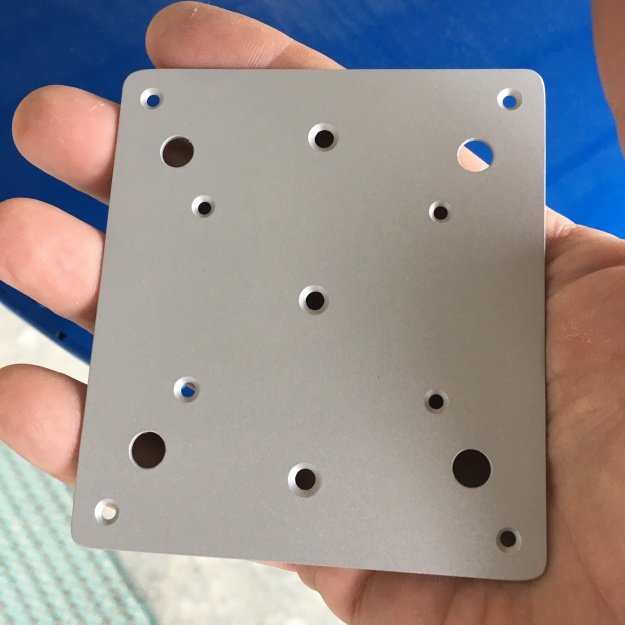
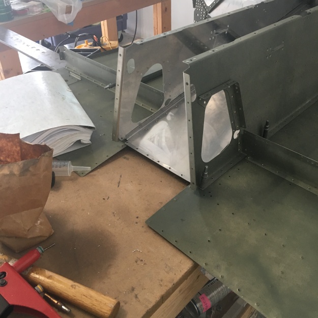
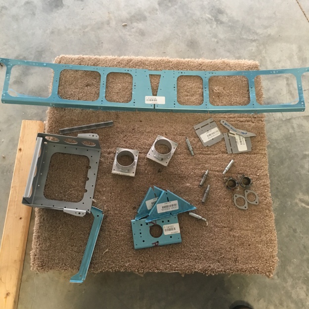
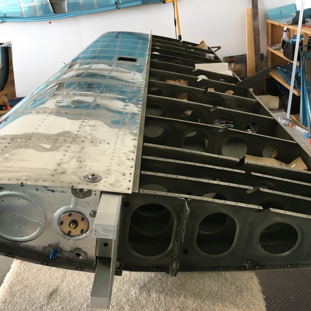
With the structure in place, it was time to shore up the wings and to add the wing fairings.  There are a couple of stiffeners that get riveted to the spar webs.  Those were pretty easy to get on.  The stiffeners require a bit of work. These are dimpled before you cut them out which is different than the normal procedure.  It did help keep straight the sides that required dimpling from the ones that went undimpled onto the plane.  There are some big nutplates that required my big dimple dies.  There are sooooo many nutplates!  The fairing look nice once they’re in place.  I can now really visualize the wings attached to the plane.

The seat brace needs some work before it is added to the plane.  There are some guides that restrain the side-to-side motion of the seats and what looks like a clamp to hold the seat covers.  It took a while to dig out the parts because it wasn’t clear that the F-01405N seat back adjustment guides were cut from a bar of black plastic.  I went through the part bins three times before I finally dug it out.  I used a marking gauge to transfer the measurements and a chop saw to make the cuts square.  The guides get rounded off.  I just did that on a sander and then used a sharp knife to trim the threads off.

Next you fit a gusset that binds the seat back bar to the skins and intercostal.  This gets match drilled in place with a lot of #40 holes drilled up to their final #30 size.  The intercostal has some tough rivets.  I really wanted that #3 offset bar to get the ones that bind the intercostal to the side rib. The roll bar brackets are bolted on.  It’s a really tight reach, even for my slender fingers, but I got the nuts on the bolts and everything torqued up.

That completed section 29 except for the eyeball vents which I’m waiting to do until I get the instrument panel in place to avoid interference — the instructions say “Delay the following steps until after the completion of Section 35 to eliminate the possibility of interference with the bottom of the instrument panel.”  So, I’m just waiting to get the area at least clecoed in place before working on the vents.

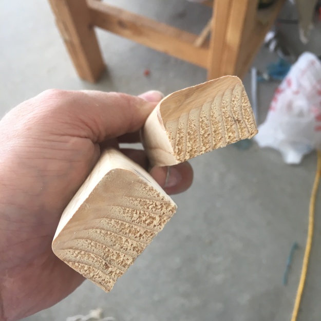
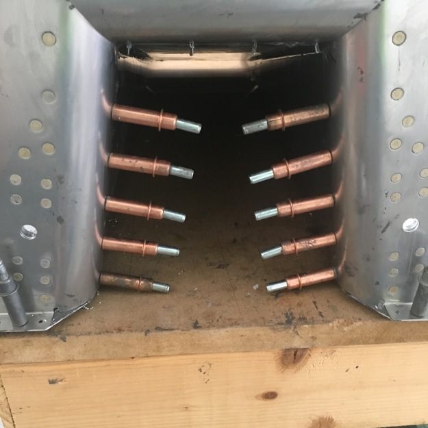
With that, I’m just about ready to take on section 30 — the big join.  Well except for one thing.  Vans just issued a service bulletin warning of cracks in the tail cone that are developing in some of the fleet.  The cracks are not particularly dangerous, but it seemed like a better idea to get the fix in now instead of later.  In particular, I have better access to the tail cone when it is off the plane instead of needed to crawl through to the back after the join.  I pulled the tail cone out of the back corner of the hangar where it was literally collecting dust and laid it on its side for access.  I used moving blankets to pad it so that I could crawl inside.  I’ve seen others that do it by standing it on end, but that seemed a little extreme.  I had no issues doing it on the ground like this. So, I drilled out the appropriate rivets and clecoed the doublers in place.  There was no way to reach both sides here, so I had to wait until my son could get down to get them all done.  I drew a matrix on the outside skin so that we could coordinate better on the rivets. I was able to back rivet all but one from the inside.  The last one was just really tight.  I was finally able to get the head of one of my yokes on it well enough to drive it.  For a weird wart of a patch, it seems really strong and doesn’t look too bad.  And in any case, it’s on the bottom of the plane!

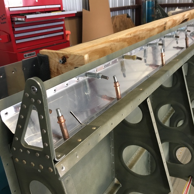
Before starting the big join, I wanted to make sure that I could really secure the fuselage parts to the saw horses.  I fabricated a spar cradle that slips into the spar from 2×6’s and a 2×4 stringer.  This way, I could screw the stringer right to the sawhorse.  It seems quite secure.  I also ran a stringer between the two sawhorses on the left so that they couldn’t accidently shift if I (or the enthusiastic dog in the next hangar) bumped into them.  I used tie down straps to help keep the back of the one half from shifting (hooked into the rear wing brackets).  The tail cone is a bit more precarious, but it still isn’t going anywhere with the longerons bracketing the front fuselage.  This piece is going to be pretty big — 15 feet or so.  It will barely fit in the back of the hangar.  I’m looking to get a larger T-hangar in California that will relieve some of these space woes.

2018-12-19 16.18.32
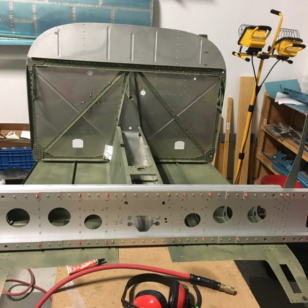
When I look aft from the firewall, I now really get an idea of exactly how big this airplane is compared to my RV-12.  I think I’m going to have a lot of fun in this plane!

2018-12-19 16.22.21-1

The next step is to get this monster clecoed together.  That is certainly a two-person job.  Once it is together, there are hundreds of rivets that are needed to complete the join.  That will be a chore!  I also have to finish fabricating a front block to let me use my rotisserie so that I can get the inside painted.  I’m supposed to be in California in 3 weeks, so I better get a move on it!

Building up the cockpit…

With the first big join behind me, it was time to start building the actual cockpit.  I started by working on the control column.  The riveting was straightforward (I’m not yet sure why exactly one of the bearings gets a very small trim, but I’m sure that Van has a good reason for it).   It was indeed a lot of fiddling to get the washers onto the bolts that hold the column to the bearing.  I dropped washers many times.  In the end, I bought a set of feeler gauges to get the right thickness selected and then super glued the washers together into a single unit that I could then insert with a washer wrench.  That seemed to work fine and the column would drop with a satisfying thunk when I lifted it and dropped it.  However, as I tested over the next couple days, I found that, depending on the temperature, it would still sometimes bind.  I’ll make one more run at the washer sets before I rivet the side skins on.  There would still be access, but it is much easier to reach with the sides open.

Next up, I had to start working on the upper longerons.  The plans call for fabricating a couple of wood blocks that sit inside the longeron so that it can be clamped in a vice.  Unlike some of the Van’s models, the RV-14’s longerons come already bent.  However, you have to add a 10 degree twist.  Hence the wooden blocks so that you can securely clamp them.  I found it took a surprising amount of twisting to get a 10 degree twist to stay.  I went around almost 180 degrees!


2018-11-17 10.57.44

With the twist applied, you cleco and match drill in the engine mount brackets.  I was able to use the drill press to keep the holes nice and straight.  Most of the rivets are normal squeezed ones, but some are cherry pull rivets.  These seemed to go in well, but I found that the mandrel on several had broken early leaving bad rivet.  I’ve ordered some replacements and luckily can pop rivet them in place even after the skins go on.  The lower longerons (which are much shorter — I guess that they are shorterons) are built similarly.


Then I have to fabricate some hinge pieces.  These hinges are used to connect the fiberglass cowling to the firewall.  You need to cut to a particular length and then remove some of the eyelets.  You only drill one pilot hole and then carefully match drill everything in place (with a shim) on each side.  I used cleco clamps to keep the hinge pieces in line while I was drilling.  I followed Van’s advice to add a cleco to every hole that I drilled.  The thing never moved.

That allowed me to pull the side skins out of storage and do a test fit.  The skin gets match drilled into the upper drag fitting and center plate.


It took considerable work to get the blue plastic off on the chilly day I attempted it.  A light touch with the heat gun helped that a lot.  Then each skin gets marked for breaking the edges, radiusing the skin at the cockpit entry rail, and a dimple free zone near the wing.  I nearly forgot to feather the back corners, but caught that when I was checking the directions.  The skins each took a lot of work to prepare.  First I broke the skin edges, but deburring the edges was time consuming with long expanses and a wiggly skin.  There are a couple holes that need to be deburred as well.  The NACA vent opening needs special care.  You want to keep the exterior edge a sharp corner to make the vent as efficient as possible.  Once that is done, you have to dimple and dimple and dimple some more.  It was easier to do this with my C-Frame instead of the DRDT-2 because I could move the frame to the hole as needed instead of trying to move the skin around.  Also, the work tables were full of partially assembled cockpit and it would have been difficult to set up there.   With the dimples done, I then washed and prepped the surface with Comet and a red Scotchbrite pad.  I put the finished skin up on sawhorses to aid in rinsing it.  I used my heat gun to force dry the skin before priming the inside.

Since the skin is flush, I had to do about a bazillion countersinks in the four longerons to match.  Similarly, the center plate had to be countersunk for every dimpled hole.

x

The next order of business was to find all the accoutrements that get attached to the skins over the next set of pages.  It is nice that they are (mostly) all identified up front.  With the part count in the bins dwindling, it is getting much easier to find the parts quickly.   The plans detail how each one is dimpled, separated, and broken.  It is a lot of parts.

2018-11-23 10.47.38

Hours later, I had all the parts appropriately prepared and scrubbed and ready for primer.

Pages 29-10 and 29-11 mostly detail part prep, but it does instruct you to rivet the angles to the intercostals.  These are 4-6 rivets and most can be easily squeezed.  The two closest to the angle are too tight for squeezing and have to be done with a rivet gun.  With the parts clamped to the bench, it was an easy shot.

2018-11-23 17.33.24

A few things get back riveted to the skins in the next couple pages and then the skins go on.  There are some more parts to prep, but the bulk of the parts are primed, dimpled, and ready to go.

The first Big Join!

With the firewall and floor mated, it was time to get to the first big join. The fuselage forward and the mid-fuselage need to get joined together so that the sides and longerons can be installed.  Both pieces are pretty big on their own, but joining them creates the first really huge piece of the build.  Right now, I can move any piece of the build solo, but after the join, that will not really be happening.

Before I slid the two pieces together, I had to finish attaching the cover plates (I had run out of time and had to stop even though I was so close).  This wasn’t very hard.  I could reach most of the rivets with my squeezer.  The ones really close to the tunnel had to be driven, but again they were easy reaches.  I almost mis-installed the cover plate by putting it on top of the cover ribs instead of beneath, but a careful look at the drawings convinced me to put it in the right place. This stiffened the front fuselage section considerably.


I slid the two sections together so that I could outline the overlap section for priming (as called out for in the instructions).  It was a bummer to put it together and then immediately slide them apart.  I got the area masked off for a quick primer shoot.  Both sides were primed when the parts went back together. The piece nearly fills both of my tables!  I slid the tables apart so that I could get at the joint and cleco the parts together.


It took a lot of clecos to get the pieces to mate.  Then there are some other pieces (drag fittings) that get bolted in to hold the spars apart or to secure the landing gear.  I had to dress up the gear braces because they had developed some rust spots.  After cleaning, I added a thin layer of grease to protect the steel. I also  finally got to open my pack of big 5/32″ clecos.

At that point, I was finished for the day.   I measured the spar distance because I needed some temporary 3/8″ bolts to secure the joined pieces on their side for riveting.  The next morning,  I had to fabricate a piece of wood that was 1 11/16″ wide to act as a temporary spar.  A standard 2×4 is too thin.  I ended up using my table saw to cut two separate pieces that I mated to match the distance.
2018-11-12 16.50.51


The drag fittings use some long, solid bolts.  These pass through both spars, the lower drag fittings, and the gear brace.  It was having a very hard time getting everything to line up so that the Boe-lubed bolts would slide through.  I finally gave up trying to do it by feel and  took a quick trip to Home Depot to buy some dowels.  I made 3/8″ and 1/4″ wooden tapered pins that helped immensely.  The narrow end would slide through the slightly misaligned parts and as I proceeded, the wider part of the dowel pin would naturally align the parts.  Then, I could either just tap the bolt through or use the bolt to back out the pin with everything in alignment.

My son arrived to help me get the assembly all tipped up on its side.  We picked the coldest day to do this!  The temps hovered at freezing all day.  We worked with the hangar door shut to keep the North wind at bay.

2018-11-13 15.56.22

I don’t have any of pictures of the riveting, but it was generally straightforward.  Most of the inner ones require two people to reach.  I was on the bucking bar (mostly my tungsten bar, but a couple required the long anvil bar).  The ones for the stiffeners between the spars required me sliding my arm between to get a bar on the rivet.  Some people used their long special bar from the elevators, but I was uncertain where that one was.  My hand only got stuck once 🙂    We had to quit a bit before we were done with all of the rivets because the wife had come down with a friend and we were all going to dinner.  I picked up and finished solo the next day.  We had taken the fuselage off the support and laid it out horizontal, so I had to tip the piece on its side again solo.  It worked out because I could gently slide it to the ground to work on the remaining few dozen rivets.  I had a bit of a problem finding the big 5-5 cherry rivets, but Vans support got me straightened out as to the proper bag (I was incorrectly looking for 5-4 rivets — read the instructions!).  Others reported that these were hard to pull, but they went in with only reasonable effort for me.

2018-11-15 12.17.37

With the rivets in place, it was time to final bolt and torque up the drag fittings and landing gear braces.  Again, the tapered pins made this a lot easier.

And voila!  We have finished the first big join!  You can see the tail cone sitting in the background.   In the not too distant future, I’ll be mating these two pieces together and creating the full fuselage!

2018-11-15 14.50.55

A firewall and a floor…

I still don’t have a new job (though I am busy looking!), so I’ve been grinding away at the fuselage.  I finished section 26 which gave me a huge piece to work around.  I moved it off the benches and started working on the firewall.  The section is rife with reminders that stainless steel is sharp.  I suffered a lot of little cuts and just one big one.  It turned out to be a tough section to work on, taking me a couple more days than I thought it would.  Once that was done, I tackled section 28 which finishes the muffler tunnel and floor and joins it all to the firewall (with a lot of little bits tacked on).


Section 27 – Firewall

You start by marking off the firewall pieces with parts that you will dimple/not-dimple and rivet/not-rivet.  I made a small mistake where I marked out some rivets for the battery box as “not dimple” that should have been dimpled.  This got carried over though the whole process of marking the support pieces and I didn’t catch it until the next section (not a hard fix, but a bit embarrassing).  Just a note to other builders to be careful here!  Once the two big firewall pieces are marked, you then transfer those to the support pieces and get to countersinking.  This process seemed to take forever.  There are hundreds of countersinks to make here.  It was just the first thing that I underestimated about this section!

2018-10-31 12.35.48

With the countersinks done (and the parts deburred and primed).  It was time to attach them to the walls.  You can backrivet here, but it is trickier than it looks because of the depressions in the wall.  It keeps the backrivet panel from sitting flush.  The #4 rivets take a lot of hits to set, but I got a bunch of badly set ones because I was not careful with the backrivet bar.  Sigh.  Little did I know that these were just the first of many rivets that I would be drilling out.

The corners were a little easier to squeeze.  I had to be careful not to dent the stainless which is surprisingly easy to do.

2018-11-01 11.34.48

The top part of the firewall bends backwards a little and is joined with a support bar.  Everything is joined with a fillet of tank sealant (oh, how I hoped that I wouldn’t have to open that smelly can anymore).  It made things pretty messy.  These rivets were set with either my backrivet bucking bar, my tungsten bar and mushroom set, or backriveting with the tungsten bar in tight quarters.  Many tough ones to set because of the large, flimsy structure.  I had to drill out a lot of bad rivets.  It got so bad at one point that I had to walk away for an hour.  I used the time to better organize my rivet collection.


Just as I was finishing riveting the center section, I noticed that I had not inserted the joggled part behind the top section. This caused some gapping and I didn’t think that it would preserve the proper integrity of the firewall, so I had to drill out the entire triangle.  I got pretty good at it.  I started with a #40 drill which helped keep me from hitting the side of the hole and then used the #30 to get a hole to break the head off.  It all came back together nicely.


The six firewall bolt holes have to be reamed to 3/8″.  I couldn’t figure out a good way to get them to my drill press, but in the end, I was able to bring my drill press down to the floor and get all the holes.

2018-11-05 10.02.37

And finally, you have to add a bunch of nutplates and a doubler plate for the relay to the firewall.  A lot of people complain that Van’s is making all the location decisions for you, but I think it will help me a lot having these important things in “good” positions.  And it is much easier to place them now instead of when I have the engine mount and engine in place.  I primed these because they were dissimilar metals touching, but I then sprayed them with high temperature enamel (made for BBQ’s and grills).  Should be fine even in hot areas beneath the cowl.

2018-11-05 13.15.48

Suddenly, I  had a firewall!

2018-11-06 08.42.46

Section 28 – Fwd Fuse Lower Structure

With the firewall behind me, it was time to work on the floors.  This part of the build made it feel like a real airplane.  I was working on parts that would literally be exposed to me when sitting in my finished plane.  I pulled the floor sections back out and started dimpling (both #40 and #30 sized holes).  There are a few areas that don’t get dimpled.  The tricky one is the “drain hole” that I marked with an “x”.  The square area in the upper left is dimpled, it is where the comm antenna doublers go.  I was treating that a little differently (see below).

2018-11-06 11.02.29

The comm antenna doubler plates have to have a good ground connection.  I didn’t want to have primer between the two aluminum sheets.  I decided to clean and backrivet these together before priming to maintain a good clean ground.

2018-11-06 11.52.12

Then you start on the actual exhaust tunnel.  In retrospect, I think adding these clips after riveting the tunnel would have made it a lot easier to get clean rivets.

I got the tunnel and floors riveted together.  Some I could back rivet, but as the triangle shrinks, I had to get more creative.  The last couple had to be done with indirect riveting.  I have a large steel brick chisel that let me get some steel on top of the rivet and then hit it with the mushroom head on the backrivet bar.  Not the prettiest, but it will do.  Oh, and of course this is done with tank goop oozing out everywhere!

The tunnel section then gets joined with the firewall.  The sides are done with pull rivets because there isn’t any room to get to them.  The top section is done with driven rivets.  I tried to do them solo, but had a rough time of it, so I waited on my son to come down and help me.

2018-11-07 11.06.10

The next part starts joining the tunnel with the shroud.  It is a clever design to provide a nice air gap between the hot tail pipe area and what becomes the center console area.  While I was manuevering things around, I stumbled and twisted a piece of the stainless across the base of my thumb.  It looks worse than it actually was, but it did fulfill the blood sacrifice requirements of the build.


Next, various parts get added to the final structure.  Here is part of the cover structure that will contain the controls in front of the seats.

2018-11-07 11.06.22

Then here the firewall gets firmly attached to the floor structure.  These plates are where the cowling will screw into fuselage.  This is literally the most forward part of the aluminum structure of the plane.  Everything else is “firewall forward” (engine mount, cowling, systems, etc…).

2018-11-07 17.06.06

There are still many things to attach at this point.  I scavenged through the parts bin and found most of them (cover panel, battery box, hot air vent controls, a couple of firewall penetration parts).

2018-11-07 17.12.58

I thought about back riveting the tunnel sides, but it seemed like it would be a tough reach in a few places.  I ended up tipping the whole structure and used my standard bucking bar and the mushroom head on the rivet gun.

Then I lay the structure flat again and added the forward bulkhead.  It gets screwed and riveted to the tunnel, and then the cover ribs get attached to the cover plate.  I got most of these with the squeezer, but where it got tight, I just used the rivet gun with a 3/32″ universal set.

2018-11-08 14.01.08

To join with the floor, it seemed a lot easier to work from the side, so I tipped the floor section up again.  I was worried that the heavy bulkhead would tip, but with the cover ribs flanges riveted in and the 1/8″ clecos, it held just fine.  Pretty simple reach with the tungsten bar and the mushroom head set.

2018-11-08 14.44.59

I don’t have many photos of the next day’s work,  but I started adding the bits and bobs to the back of the firewall.  I had to tank seal the penetrations in, fabricate the hinges for the vent doors, rivet the doors on, and then rivet on the battery box into place. There, the only hard part was countersinking the battery box.  It had to be done by hand because with the bends in place, there is no way to get my countersink drill set into play.  Here’s a picture of the “before” view.  I didn’t quite get the last piece in (the cover panel) because I ran out of time (I had to get home early to work on some honey-do items).  I also lost some time talking to a few recruiters about jobs.  ‘Cause I really do need a job.  Meanwhile, I’ll finish section 28 in about an hour and then start on the first big join!

2018-11-08 17.51.41

A lot of fuselage time…

Well, I quit my job at the beginning of the month… I’m busy looking for the next thing — this just wasn’t the right place for me, so I decided to move on.  Meanwhile though, I’ve been relentlessly grinding away at the fuselage.  You can make a lot of progress when you work (nearly) every day!

It is almost certain at this point that I’ll be leaving Houston, so some of this work is designed to make it easier to load up the kit and roll it down the road to the next stop.  The wings are in good shape for this.  They are sitting in their nice low cradles with just the bottom skins, the pitot mount, and a few brackets to rivet into place.

I had been trying to finish out the wings, but lost momentum as I was working on the aileron controls.  I messed up one of the control rods and had to order a replacement.  That’s come from Van’s, but by then I was deep in fuselage mode and will return to the wings later.

Section 25 — FWD MID FUSE BULKHEADS.

So I dove into the first section.

This was mostly just bolting and riveting on various cover ribs, side angles, and miscellany onto the three main bulkhead bases.  The forward most one has the cover ribs, the second one holds the seat ribs and the final one holds the baggage ribs.

2018-10-06 17.41.01.jpg


The bulkhead bars are pretty hefty.  They are bolted onto the bulkhead.  To get the alignment right, you just slide a bolt through the final attach point which is sitting super accessible on the end of the wing! I love it when the parts I make look just like the plans!

I didn’t take a lot of pictures working on the bulkheads – the work was mostly monotonous. The silver nuts are temporary ones since the bars will come out and be slid in again later. The seat back brace is still in blue because it is just a temporary measure to help keep the side channels square.  Most of the rivets have to be driven — only a few can be squeezed.

Section 26 — MID FUSE LOWER STRUCTURE.

This section is huge!  I can’t imagine how many months it would take me to finish at the “most Saturdays” pace I was working at.  It has 22 pages and lots of parts and lots of riveting to do.

Section 25 — FWD MID FUSE BULKHEADS.

So I dove into the first section.

You start by adding some doublers to some of the baggage ribs.  These had a lot of “curl” to them, so I just choose to mount curl down.  The rivets hold them flat in any case.


Next, you start preparing the baggage and seat ribs.  Lots and lots of deburring work.  I managed to stab myself with a file as I was working one of the doublers.  We have a saying around the house, “It’s not a project until you donate some blood to it!”

2018-10-17 11.13.03.jpg

The ribs all get a collection of clips, doublers, and nutplates — oh the many, many nutplates I had to install.  Each rib is a little bit unique, so careful attention to the plans is warranted here.

Finally, you start building real structure again!  The seat ribs feature a mount for the crotch strap (for a 5-point harness).  It struck me that I was now building parts that I’ll use and see when the plane is done (rather than working on ribs buried in the fuel tanks).  Finally, you get to rivet the seat ribs to the bulkhead — starting to look real!

In the midst of this, you break out the big floor skin that really defines the mid-fuselage.  You have to flute the outboard seat ribs to follow the curve of the skin.  It wasn’t very hard to do… Just had to sneak up on the curve.  The holes lined up very nicely without having to mess around a lot.  You can see from the second frame that the curve is pretty big before the fluting!

The baggage ribs don’t have as many doo-dads to connect as the seat ribs. But they do have a lot of nutplates!  Also, you have to build out an idler bracket to attach to the bulkhead.  The only tricky part was bending an extra flange into each side.  I couldn’t get this to mount in either of my brakes, so I bent it by hand.  Just got it started in my vice and then finished with my flanging tool.  They came out pretty clean.

Then you add some more seat belt lugs.  The instructions have you rivet the top end together with an AN4-5 rivet, but I later had to pull these to get them to go through the holes in the bulkheads.

Then you have to start cutting into the big bottom skin and the two footwell forward skins.  It isn’t really clear, but the bottom skin is NOT symmetrical!  If you look closely, you can see that there is an extra set of holes on the right fuselage.  It’s in the pictures, but it’s never mentioned in the instructions.  Well, as luck would have it, I choose the correct side!  Probably not the end of the world if I hadn’t, but then I would have a comm antenna on the “wrong” side, I suppose.  The instructions suggested using a die grinder to remove the rectangles of aluminum (for the gear mains on the nose dragger version I’m building — not needed for a tail dragger).  That seemed like a crazy idea, so I used a drill and then rough sawed them to the correct dimension, then snuck up to the final line with a bastard file.  It didn’t take too long and the result was crisp and clean (but my arms were pretty tired afterwards!).  You also have to enlarge certain holes (different sets for tail and nose draggers).  I’m always vaguely terrified when I use my step drill.  I worry that I’ll click through one too many holes.  I mark the target ring with a sharpie so that I can see when to stop!

Then it’s time to dimple the bottom skin.  It’s really big!  I managed to do the whole thing (almost) on my DRDT-2 dimpler all by myself.  It is a mix of 1/8″ and 3/32″ holes that need to get dimpled.  And there are a few exceptions (I used orange tape to mark these).  This took a while.  If nothing else, it took me 10 minutes just to get the blue plastic off!

There was one dimple that I just couldn’t reach. It was about 1/4″ too far to get at from any angle.  Rather than pop rivet dimple it, I just put the female die into a holder and then used the C-Frame holder and a hammer to gently form the dimple.  It worked great!

You then build a mini-bulkhead in the front of the compartment.  This creates one the attach points for the main gear assembly (the seat ribs will straddle this).  That explains the hefty doublers that form the heart of it.  It is important here to get the little vertical seat attach angles straight up and down.  Later, you’ll slide the seat rib assembly right over it and you’ll be glad you got it right now.  I just clamped the brace to a square and it came out great.  The whole thing is riveted in place onto the bottom skin.  When you’re sure that it’s right, you squeeze the final rivets in place.  The second brace goes on after you get this onto the skin.  I just made careful measurements to verify that they were parallel.

Then things get big very fast!  You take the seat rib assembly and cleco it to the bottom skin.  I wasn’t careful about sliding the outboard ribs onto the correct side and didn’t notice until I had already done some riveting.  I managed to slide them past the braces so that the joggles were lined up correctly.  My son stopped by to help me rivet these.  We got almost all of them with my back rivet bucking bar.

With those done, you just pop-rivet the vertical braces onto the appropriate seat rivet and then add a power outlet bracket.

At this point, you go back to the baggage ribs.  They have detailed dimpling instructions.  Then you have to build out a structure to hold the steps (optional for the tail draggers, but it’s a big step for the nose dragger otherwise!).  Most of these are driven, but a few are cherry pop-rivets because the angle is too tight to get a squeezer or bar in to make the manufactured head.

As you build up  these sub-sections, you then attach them to the big assembly.  As I noted, I could not get the seatbelt lugs to pass through the holes with the end rivets, so I just drilled the out and re-squeezed them as I went.

I had to wait for bucking help to finish these off, but they came out looking great when I finally got to it!  After all those rivets, there were a couple little tasks to get to before closing out the section — A baggage floor stiffener is added and then the outboard baggage ribs are slid into place and riveted to the floor.  Whew!  21 pages done!


Next up… the firewall!

Still dragging my way through the wings

Spent most of the long weekend working on a project for my brother… He wanted to make some replica B-17 nose art.  So I fabricated a 26″x26″ fuselage section.  It’s curved with two ribs and two stiffener and some AN470-4 rivets.  It came out pretty nice — it just took a bit longer to build than I hoped.

Then I got back to work on the aileron control rods.  I primed the main rods and started to assemble.  I was short some of the cherry max rivets, so I had to defer further work (and get an order out to Aircraft Spruce so I can have them by next weekend!).  One of the mandrels got stuck in my puller, so I had to break out my father-in-law’s trusty puller that worked like a champ.

2018-09-03 13.42.57

So I started working on the gap seals.  The blue plastic was really clinging to the aluminum.  This does not bode well for when I pull all the old stuff off.  I had to strip off the adhesive with a large dose of acetone.  The worse news was that when I went to go dimple the seals, I found that my trusty Main Squeeze’ cam had broken.  It just doesn’t reliably go up and down.  So that meant that I had to bang out another order to Cleveland Tools since I don’t see a way to make much further progress without a good hand squeezer.  I did make some progress  by dusting off my pnuematic squeezer, but while it was fine for dimpling, I found that was having problems actually squeezing rivets (it may be because my air compressor seems to max out at 90 lbs pressure these days).  Sigh.  At least the new tools and replacement rivets should arrive before the weekend.

2018-09-03 16.46.23

I had to do some work to actually fit the seals onto the wing.  The new aileron attach brackets are a bit larger and beefier, so I had to trim one end and make sure there is no interference (and no stress corners).

2018-09-03 17.17.37

So, next week I’ll hopefully have the gap seals on and the aileron rods in place.  I made sure that I will have all the AN hardware (I ordered some extra from Aircraft Spruce to make sure).

Lots of little things to finish on the wings

I’m still working on the wings.  There are a lot of little steps that I skipped past when I did this kit out of order.  Now that I have the wings mostly in one piece, I’m catching up and getting to them.

The wings are in a wing stand now.  I built a new one because I wasn’t happy with the old one and didn’t want to use the “sling” style to hold the wing up.  I just assembled the wings flat on my tables.

2018-07-14 17.29.12

When done, I tipped them into a lower stand made out of 3×4 plywood ends.  My son stopped by the hangar after his flying lesson and helped cut them out.  I just used a rib end and the leading edge tipped on its side to get the outlines.

Then I just added some 2×4’s to hold it all together with some castering wheels from the old stand and voila!

With the wings together and accessible, it was time to clear some of the backlog…  The wiring harnesses look deceptively simple to install.  They do pretty much just thread through the ribs in the grommets I installed oh so long ago, but you also have to correctly isolate and install a couple dozen wires into Molex connectors.  So, it involved lots of staring at the wiring diagrams and tugging wires to make sure I had the right white wire for pin 12!  Eventually, I got everything in the right place and did some initial zip tie work.

Another thing that was left hanging was addressing SB 16-03-28 which covered a potential for cracks in the spar at the aileron attach bracket.  This is one of those “inspect and fix if found” annoyances, but I wanted to be in front of it (in part because it is hard to inspect and a royal pain to fix if found.  With the bottom skins off, however, it is relatively easy to accomplish because I had access to both sides of the spar for drill out and for squeeing new rivets.

First up, I removed the old brackets and recovered the bearing (it gets reused in the new bracket).  The old bracket had a thick aluminum piece sandwiched between two thin bent pieces.  The new bracket has two thick pieces and super thick angle irons and a doubler plate and a secondary brace.  Even just clecoed in place, it is much stiffer with no discernible flexing.

Of course you have to go through the whole, cut out the pieces, file, deburr, etc… shenanigans.

2018-07-29 16.18.17

It was a bit tougher to squeeze the rivets than I thought it would be.  The clearance was really tight.  For the first one, I built the full bracket and then tried to rivet to the spar.  This didn’t work well because the bracket rivets interfered with the spar rivets.  I smiley’d three rivets with the squeezer and the offset rivet set before I got wise and ground down the squeezer yoke.  This got me 7 of the 8 rivets.  I had just purchased a 5.5″ yoke that I was able to use to get the last one.

2018-08-25 17.27.34

I still need to put the skirts on here and those will need a minor trim job to fit around the larger brackets.

Finally, I got to work on the aileron control rods!  It took a long time to dig out all the parts.  The wing kit parts had become a bit scattered over the last two years.  Plus I have already unpacked the fuselage kit which adds to the clutter.  I finally dug out all the rod ends and found the 1 1/8″ and 1/2″ tubes and the torque tube collar piece.

I cut the rods to length using a chop saw with a metal cutting blade.  The 1 1/8″ tube is thin walled aluminum and cut easily.  The 1/2″ powder coat tube, however is steel, so cutting it gave me a spectacular shower of sparks.  With the cuts made, it was time to pilot drill the 6 holes on each end.  I used a cheapo Harbor Freight V-block in my drill press.  It worked great.  It would  have been difficult to control without the block.  Once the pilot holes were done (and roughly deburred), I slid the rod end pieces in to match drill them the same way.

With that behind me, it was time to final drill to #30 and swap the silver clecos for brass ones.

2018-08-26 15.05.04

The tubes and rod ends are raw aluminum alloy and need to be primed — inside and out.   Another builder I saw online was clever and taped off the end of the tube and poured in primer and then inverted the tube to let it drain out.  I did this, though I had a catastrophic containment failure when the tube end tore my glove and lacquer poured all over my hand.  I also primed the rod ends (after carefully labeling them so I could get them back into the right tube).

Next week is a long weekend, so I should have some time to finish out the aileron actuators.  I should also be able to get the gap fairings installed.  At that point, I really only have to finish the bottom skins for the wings.  I’m going to defer that until I really have to.  It’s nice having good access.  Plus, once I cleco the skins on, I’ll have them out of the way so I have enough room to start work on the fuselage.

Wings finally coming together

It’s taken a while, but the wings are finally coming together.  With both tanks finally finished (there was a trivially easy to fix leak in the second tank in the corner where the tank attach bracket met the inboard rib… I just syringed some proseal into the gap and it closed up nicely), it was time to move on with getting the wings together.   I had a couple of projects on the leading edges that I had to finish.   While still in NY, I waited to finish the landing light covers because I didn’t want to finish them in the sub-zero temps.  Well, here in Houston, it was a balmy 94 degrees.  No more excuses.  The fit is OK, but I feel that I could have gotten a better seal.


I was thinking about building over the 4th of July holiday, but instead spent a nice day down at the Lone Star Flight Museum.   They had the B-17 open for tours.

2018-07-04 11.11.29

With the lenses in place, I fitted the stall warning switch.  I debated leaving this off since I’m planning to install a Dynon heated pitot with angle-of-attach sensing.  However, it is such a simple device that will help more than hurt, so I left it in.  I can always disable it or remove it if I find it burdensome.

With that, it was suddenly time to start assembling the wings.  The leading edges are permanently installed (rivets for the ribs, driven rivets for the skins).  I started with the LP 4-4 and LP 4-5 rivets that hold the inner ribs in place.  It is a tight squeeze, but it is so much easier to do this without any proseal clogging things up.  I used my father-in-law’s pop rivet gun here because it has a very narrow head which let me get in right next to the ribs.

Then I started to get the fuel tank in place.  Here, I only have a few bolts holding it in place, but it really looks like a wing now!

2018-07-07 16.59.57

Next week, I’ll finish the left wing (bolts and screws for the tanks and the rivets that I can reach for the leading edges) and get started on the right.  I’m building a new wing cradle that can better hold the wings at this stage and prepare for riveting the bottom skins and applying the spar strengthening service bulletin.  I’ll leave the bottom skins off until closer to wing attach point.  It is much easier to initially fit the aileron controls, for instance, with the skins off.  Same with getting servos and pitot masts and and other things fitted.  It will move up the day to start on the fuselage as well!

After a long hiatus… tanks — a lot!

I’ve haven’t blogged anything in almost 9 months, but I’ve been very busy.  I spent a lot of time working on the my RV-12.  The condition inspection (more specifically, my updating the radio and adding ADS-B In/Out (a new GPS antenna and a new ADSB-In antenna) really kicked my butt.  It dragged on and on.

But through it all, I kept grinding away at the tanks.  It was really slow going.  Mostly I think that this was mostly mental.  I knew that I would have to break out the ProSeal and I kept prevaricating and didn’t get to the end.    Well, finally, I just decided it was time to dive in, so I did.  There aren’t a lot of pictures because my hands tended to be covered in grey, icky goo most of the time.  These pictures will cover many months work.


The fuel and drain fittings went in much more smoothly the second time through.  I was finally getting the hang of working with the sealant and got my riveting groove back after being out of practice for so long.  I got a nice squeeze out and made sure to thoroughly cover all the possible places it might leak.

For some reason, I was really looking forward to getting the fuel caps installed.  Maybe it’s just the nice contrast between the anodized red filler and the (not so) shiny aluminum.

Next, there is a lot of back riveting to do.  I tried masking off the areas around the stiffeners, but found that (1) it didn’t really help keep things clean and (2) it made it hard to form a nice bead of sealant.

I took the leading edge stands and built a little rotating adapter that I strapped to a low bench.  This proved very handy for getting a good angle for the riveting work.  This put the wings at a comfortable height and allowed me good access to both sides.

Another thing that proved handy was having small plywood backing boards.  These fit inside the ribs and made them straight and stiff for inserting whilst covered in sealant.  Also, if I needed to, I could give them a gentle tap with a dead blow hammer to get them to sink into place.  I highly recommend making a pair.  They just flip over to do the other tank.  One is long (for tapping) and the other sits inside the flange to give some strength when bolted together.

I also cut another piece of plywood cut slightly bigger than a rib.  This was useful for gently spreading the skins apart when I was sliding the ribs in.  It helped get the skin into the right shape and made just enough room to slide the next goopy rib into place.


The riveting was very messy.  I got everything together though and obsesses over covering each rivet head.  The J-stiffener was pretty hard to get in with enough sealant.  The instructions suggest that you can slide it in without touching the skin, but I found that I dragged off some of the sealant anyway.  I added a little more on the insertion side and it seemed to achieve good squeeze out.


I needed to fabricate the vent line.  One open end sits at the highest corner of the fuel tank (near the filler cap).  It comes back to a fitting on the inside rib (where the flare fitting is).  It was my first flare (I used my father-in-law’s flaring tool, so I didn’t have to buy one).   It came out very nice with no cracks.


In April, I was headed out to a conference near Portland, so I had to stop in at the mother ship.  It was a Friday, so the factory floor was empty, but I still got a nice tour and got to sit in the original 14A!  It was much roomier than I expected (and a bit taller).  It certainly reinvigorated my desire to get working again.

When I got back, I finally got around to fabricating the fuel floats.  I know some people put in capacitance senders, but this seemed so simple and basic that I didn’t want to stray from the plans.


Then it was time to seal up the rear baffle on the first tank.  I was pretty nervous.  I checked everything multiple times.  I had a lot of trouble, though, with the pull rivets.  I kept getting sealant in the puller which would then seize.  My trusty Stanley puller gave up the ghost, but I finally got everything pulled.

I took the first tank home to do the leak testing.  I put the balloon on and it seemed to hold air.  I took a dip in the pool and checked back a couple hours later and found that it was totally flat.  That weekend, I got some bubble juice to try to track down the leak.  It was at the balloon joint itself.

So off with the pink balloon and tube and on with a directly connected green balloon.  I added a little Gorilla tape to buffer the clamp so that it wouldn’t cut the rubber.  This one held for 24 hours.  One tank done!

So I did the second tank last weekend.  Brought it home.  Put a lucky green balloon on and….

There was a definite leak at the corner of tank inboard rib and the tank attach bracket.  Sigh!

It could be worse.  I think that I can vacuum in some thinned sealant to get a better seal (or maybe some LockTite).  If that fails, I can reach it by taking off the fuel level sender (yuck), but at least there is a hole that I can reach it through (or a tube attached to a syringe anyway).

In preparation for attaching the tanks and leading edges, I worked on finishing the leading edges.  I had skipped fitting the landing light lenses because it was cold (in NY!) when I last touched these.  It was a balmy 96 degrees F in the afternoon, so I was less worried about cracking.  The first lens has a small gap.  I hoped that I would get a better fit.  I’ll just use some silicon or something to make it watertight after final install.  The second on went on very nicely and I achieved a nice fit around the leading edge.  I changed my technique for the second one and drilled and clecoed the holes directly into the lens after the first rough cut (3/4″ margin).  This let me push harder on the lens from the inside and get that tighter fit I was trying to get.

So next steps are to patch the leaky corner in the second tank.  I’m hoping that it won’t be too hard to get to.  It takes a while though between iterations since I have to let the sealant cure a bit before testing.

Next, I will do the first rough assembly of the wings and fab the control rods.  There’s also a service bulletin that I need to get to that increases the doubler at one of the control mounts. I may even get the pitot mast mount installed.  I’ll wait to close up the bottom skins for a while so that i can get started on the fuselage.


Fuselage is here!

Not a lot to post, but my fuselage kit was just delivered… Of course I thought the wings would be almost done by now.

I was supposed to get a call from the trucking company to give me an hour heads up before the delivery, but the call never came. I headed out to the hangar at 3:30 because the kit was supposed to arrive by 5pm and traffic was building.

Finally, after 3 calls to dispatch, they got a hold of the driver who had been delayed by an exploding pallet.

Got it off the truck and into the hangar. Then I had to run because the wife and I had tickets to "39 Steps." Made it with time to spare!